|


Drawing Sheet Layout
Standard layouts of drawing sheets are specified by the various
standards organizations.
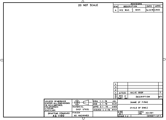
This is the layout of a typical sheet, showing the drawing frame, the
microfilm camera alignment marks, a typical title block, parts list and
revision table:

Sheet Frames
It is standard practice for a drawing frame to be printed on each sheet,
defining a margin around the outside of drawing area.
Drawing frames are standardized for each size of paper as per the
following table:
Drawing Frames with No Filing Margin
| Paper Size |
Border Width (mm) |
Dimensions of Drawing Frame (mm) |
| |
Left &
Right |
Top &
Bottom |
Width |
Height |
| A0 | 28 | 20 | 1133 | 801 |
| A1 | 20 | 14 | 801 | 566 |
| A2 | 14 | 10 | 566 | 400 |
| A3 | 10 | 7 | 4003 | 283 |
| A4 | 7 | 5 | 283 | 200 |
Title Block
The title block is normally placed in the bottom right of the drawing
frame, and it should contain the following information:
- the name of the company or organization
- the title of the drawing
- the drawing number, which is generally a unique filing identifier
- the scale
- the angle of projection used, either first or third, generally
shown symbolically
- the signature or initials of the draftsman, checker, approving
officer, and issuing officer, with the respective dates
- other information as required
Material or Parts List
If the drawing contains a number of parts, or if it is an assembly
drawing, a tabulated parts list is attached to the bottom right of the
drawing frame, just above the title block.
The parts list should give the following information:
- the part number
- the part name
- the quantity required
- material specifications
- the drawing number of each individual part
- other applicable information
When the parts list is very large a separate drawing sheet may be used
for the parts list alone.
Revision Table
A revision table is normally located in the upper right of the drawing
frame, or at the bottom on the left side of the title block.
All modifications to the drawing should be documented here.
Zoning
A drawing may be divided up into a grid using letters and numbers. When
zoning is used it is located inside the drawing frame.
Zoning allows easy references to various parts of the drawing by
referencing a coordinate such as C7.
|

|


